|
Introduction
In February '06, I decided to replace the carburetors on my '82
Yamaha XJ1100 Maxim motorcycle with an electronic fuel injection (EFI) system.
I also replaced the ignition system.
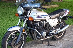
The XJ1100 motorcycle is an inline 4 cylinder engine, producing approx. 90 hp at 5500 rpms. This project took about 7 months to complete, working nights and weekends. During this time, I left town for 5 weekends, including a wedding, two reunions, an offshore fishing trip, my spring bass fishing trip, and the birth of my grandchild, Katherine. When Houston Summer's arrived my motivation slacked; just too darn HOT to enjoy the garage. I also had a full time job and there's always home chores; remember it's a hobby; I also own a Honda CB900F Super Sport to "keep me satisfied". Stan's Photo Gallery
|
|
| Stan and his '82 XJ1100 Maxim motorcycle. | |
EFI-ing a motorcycle is NOT easy, however, the results are very rewarding. If you decide to install EFI on your motorcycle, find a partner and make this project an adventure. It also makes it more fun and puts another set of brains working "the little things."
The Little Things
I found lots of "little things" tripping me up, and causing lots of
delays. I'm laughing at them now, but during the "heat of battle",
I found them "madding". I'd start a task, and then get stuck for several
nights or weekends trying to solve the problem, finding the right part, or locating
the wiring error. It drove be crazy and extended the project. I'm writing this
to help others (and record my adventure.) I hope you learn from my mistakes,
save some time, and enjoy the technical experience. Here's a list of some of
my miscues:
| Parts Description | Source | Unit Cost |
| MegaSquirt Programmable EFI System PCB3.0 Unassembled Kit | DIYAutoTune.com | $189 |
| MegaSquirt Stimulator Board Unassembled Kit | " |
$40 |
| 2 foot Wire Bundle - Same wire used in harness color coded and printed labeling. Great for wiring up connector to the factory connector. | " |
$12 |
| 6 foot DB9 male / Female Straight Thru Serial Cable - Used to connect the MegaSquirt EFI to a computer | " |
$6.50 |
| Shipping and Handling from DIYAutoTune (Duluth, GA) | " |
$9.70 |
| 6400009, 8 oz solder 0.032 dia. 60/40 formula (Note: A 2.5 oz spool of solder is plenty.) | Radio Shack Electronics | $8.39 |
| 6402086, De-Solder Bulb (Get a solder wick instead of this bulb thing.) | " |
$3.19 |
| 6402052, 15 watt replacement tip | " |
$0.99 |
| 6402991, Helping Hands w/ Magnifier | " |
$12.99 |
| 2761995, two (2), PK2 8pin IC Socket | " |
$1.38 |
| 2761998, PK2 16 pin IC Socket | " |
$1.29 |
| 2750409, PK2 Slide SPDT Switch | " |
$2.49 |
| Texas Sales Tax | " |
$2.38 |
| 65" of throttle cable, cable sheath, locking-nut at the Throttle body, and two ball ends. | Texas City Cycle Kawasaki, 1119 6th Street, Texas City, TX 77590 (409-948-4969) |
$30 |
| three (3), 497-2005-5-ND IC Dvr/Rcvr 5V RS232 16 DIP | Digi-Key Corp. | $4.17 |
| three (3), PB685-ND Relay Auto SPST 30A 12VDC QC Brk | " |
$6.06 |
| Handling Charges ($5 minimum handling charge for orders under $25.) | " |
$5 |
| two (2), PK-82 Chromed Cap High-Flow Bike Filters, ID In./MM: 1 7/8" to 2 1/16", 50-52mm / Height 3" (UNI POD KIT PK-82) | Cyclepages.com 540 West 38th Street, New York, NY 10018 (212) 268-3854 |
$30.56 |
| UFM-400 Air Filter Service Kit | " |
$12.95 |
| Shipping | " |
$9.99 |
| Computer Serial Interface Board | Best Buy | $30 |
| 1999 Suzuki Hayabusa inline Fuel Pump and Shipping |
eBay | $81.00 $12.65 |
| 2005 GSXR 600 Throttle Body and Shipping |
eBay | $50.00 $12.01 |
| In-Line Fuel Pressure Gauge , 0-60 psi, Nissan , Toyota, Honda,etc. Shipping and Handling |
eBay | $16.99 $5.95 |
| Pack of 5 and 10 Amp Mini Fuses | AutoZone Auto Parts | $4.98 |
| Crank Position Sensor | " |
$17.99* |
| Texas Sales Tax (8.25%) | " |
$1.89 |
| 15729 Bosche, Universal Oxygen Sensor | O'Reilly Auto Parts | $59.99 |
| 73520 Silver hose / wire cover for the crank position sensor | " |
$5.79* |
| WT382 Temperature Sensor | " |
$18.99 |
| TW3000 Temperature Sensor | " |
$15.99 |
| four (4), OMS 8DQ19 Spark Plug Leads, 19" | " |
$15.96* |
| WIX 33484 Fuel Filter | " |
$14.99 |
| four (4), NGK 7131 Spark Plugs | " |
$6.36* |
| Six (6), Buss BPHHM Fuse Holders (Note: A 6 slot fuse bloc would work better, and look neater.) | " |
$10.74 |
| 6 ft. of Fuel Hose | " |
$5.34 |
| Texas Sales Tax (8.25%) | " |
$12.71 |
| O2 Bung | Meineke Discount Muffler | $6 |
| Labor to weld the O2 Bung on the exhaust pipe | " |
$25 |
| Two (2) connectors for the GM DIS ignition | Auto salvage yard | $10* |
| one (1), GM DIS ignition system with two coils | Best Auto Parts, They gave me the DIS system at no cost (free), but $75 is a good estimate. | $75* |
| A 6"x10"x3/16" steel sheet and a 1" diameter steel rod (material for making the DIS induction plate) | Welding shop near my house | $10* |
| Misc. hardware, nuts and bolts, drill bits, etc. | Tucker's Hardware Store (Great folks) | $50 |
Sub-Total Ignition Parts |
141.10 |
|
Sub-Total EFI Parts |
824.25 |
|
Total |
965.35 |
* Ignition parts
Anyone driving a newer cars know their advantages; I like two reasons -- environmental (big deal) and performance (BIG Deal). The best reason is money; EFI systems are cheaper to manufacture and easier to maintain; and they can improve your fuel economy. Their disadvantage is complexity; electronic systems, especially on motorcycles, can reduce reliability and availability. Everyone knows this rule, “Keep It Simple”; Complex systems fail more often.
Electronic systems have come a long way…welcome MegaSquirt.
MegaSquirt
Bruce Bowling and Al Grippo, developed a Build-It-Yourself, EFI
system. Their web sites,
MegaSquirt Electronic Fuel Injection Computer and MegaSquirt
FAQ's, provide a great overview. I could say more, but basically, these
two guys sell an electronics kit for EFI-ing your car or motorcycle. The kit
comes complete with printed circuit (PC) cards, electrical components, software
and documentation. And what's more amazing are the Success
Stories.
Good things just get better...other people continue to develop software tools. And just in case you run into problems, there's an EFI Forum available to answer questions and provide assistance, where needed; cause things never go as planned, "As my old daddy use to say, It's always something."
Their MegaManual Index provides the latest web-based version of the manual for MegaSquirt. It's updated frequently, and contains the latest information on assembly, testing, troubleshooting, installing, and tuning your MegaSquirt.
In Feb.’06, I decided to modernize my ’82 XJ1100.
Building the MegaSquirt Stimulator
I started my adventure by assembling a MegaSquirt Stimulator (MegaStim).
I purchase the version 2.0 board with 4 LED’s from DIYAutoTune.com.
Note: In July '06, they started making a version V2.1 board with 5 LED's, so
things have changed since I bought my hardware. I followed the instructions
exactly as written in the Stimulator
Assembly Manual. It was easy and very straight forward; and it gave me a
chance to practice my soldering skills; cause the small successes are important.
 |
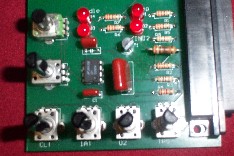 |
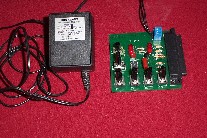
| 9 volt power supply module and stimulator. | Stimulator |
I tested the MegaSquirt controller by using the Stimulator; where you build a little, and then test a little; I liked this approach. It worked great, and provided confidence to continue. I used a 9 volt (120ac/9v DC) power supply module to power the stimulator, which also supplies power to the MegaSquirt controller when bench testing. The power supply is probably from an old phone or computer game; it worked great and sure saved on batteries.
Building the MegaSquirt Controller
I bought a MegaSquirt I EFI controller from DIYAutoTune.com
, a version V3.0 board, . It came as a complete package, ready to assemble.
I also bought a two-foot wiring harness, which is optional, but sure made things
easier during the Assembly
phase. The V3.0 board is a very professional looking product.
I bought 8 oz of solder from Radio Shack, which was about 4 times too much; I recommend buying the 2.5 oz., 0.032 dia. 60/40 formula spool, cat. no. 64-005. I also bought their Helping Hands Magnifying kit, which worked great for my tiring eyes. I'm an older guy with bifocals and this kit held the board rigid while applying the solder. The magnifying glass provided a better view of the work site. My biggest problem was lighting, or the lack of lighting. I tried a halogen shop light, but it produced to much heat and glare. I finally decided on a florescent desk lamp, which worked pretty well.
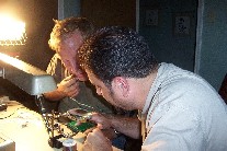 |
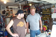
| My brother Steve and a friend Walter looking at the MegaSquirt board. |
Steve and I spent about 15 hours building the controller. We were slow but steady. The manual says 6 to 8 hours for the average person with average skills doing a first time assembly. I made a few mistakes during the assembly sequence and lost some time troubleshooting the problems. I can safely say that working a few hours each day and a little wrap-up time on the weekend, it's relatively easy to assemble the circuit board in a week.
Loading the MegaTune Software
Installing the MegaSquirt software and the MegaNSpark extension was a little
tricky; and it took me a little while to understand the process. It's like
most things in life, "Once you've done it, it's easy." Hmm, I
think they call this "experience."
The 68HC908 processor I purchased already had the MegaSquirt software installed.
However, I still needed to download the MegaTune program and install the
MSnS-E ignition software (more on this later.) For now, I needed the MegaTune
software for testing.
I went to the MegaTune
2.25 site and downloaded the mt225 setup.exe - The
standard installer. I chose the 'Run' option and all the defaults; the install
program created all the directories and sub-directories; and located the
files in the C:\Program Files\MegaSquirt directory. The installer also created
a file called C:\Program Files\MegaSquirt\Car1; which is
where specific motorcycle information goes. I copied the Car1 directory;
pasted and re-named it C:\Program Files\MegaSquirt\StansXJ1100.
This way I kept all the download files intact.
I followed the instructions in step 40; ran the MegaTune application, selected
the StansXJ1100 option in the popup window, and set the COM port to com4.
(The MegaSquirt manual says com1, but I think the new serial interface card
I installed set itself to com4.) Success...IT WORKED, my desktop was talking
to the MegaSquirt controller.
In step 41, I connected the Stimulator, opened the "Realtime Display"
under "Tuning" on the main menu and verified the incrementing
time and battery voltage.
Input Section Construction and Testing
External Device |
DB37 Pin outs |
Wire Color (Label) |
Comments |
| Ground Wires (5 wires total) | 8, 9, 10, 11, 19 | Black |
I connected each sensor requiring
a ground wire with one of these wires, including the TPS sensor. |
| Intake Air Temp. Sensor | 20 8 |
Orange (IAT) |
IAT input Ground |
| Coolant Temp. Sensor | 21 9 |
Yellow (Coolant) |
CT input Ground |
| Throttle Position Sensor (TPS) | 22 26 10 |
Blue (TPS SIG) Gray (5 VREF) Black |
TPS SIG 5 V Reference Ground |
| Main Relay | 28 11 |
Red (12 V) Black |
12 volts Ground |
| Left Injectors | 32, 33 |
Blue |
Cylinders 1&2 |
| Right Injectors | 34, 35 | Green |
Cylinders 3&4 |
| Fuel Pump Relay | 37 | Purple (The manual shows a greenish wire.) |
Relay coil (85) |
| GM DIS | GM Socket Pin outs | DB37 Pin outs |
Wire Color (Label) |
Comments |
| 3X Reference High | E | 4 (SPR2) |
Purple and white | LED 16 |
| IC Control (EST Timing Advance) | B | 5 (SPR3) |
White | LED 14 |
| Bypass Control | A | ??? |
Brown w/White stripe | 0 volts when cranking, +5 volts running |
| Ground (Reference) | F | 19 |
Black and red | Common ground |
MegasquirtNSpark
(Software and Wiring Mod's)
The last thing I did (to the MegaSquirt controller) was to install the MSnS-E software and hardware modifications.
Installing the MSnS-E Software:
Stan, write this section.
Making the MSns-E Hardware Modifications:
This was easy, I took three (20 AWG) wires from a old piece of telephone cable
and soldered them to the LED diodes installed in step 80; D14, D15, D16. The
other end of the wires, I soldered to the SPR-2, SPR-3, SPR-4 pads on the circuit
board, near the DB37 connector.
Stan, insert a picture.
Ignition System
Yamaha equipped the ’82 XJ1100 Maxim with a fully transistorized breakerless
ignition system. The system uses magnetic pick-up coils and eliminates the need
for breaker points.
I replaced the factory ignition system with a General Motors (GM) Distributorless Direct Ignition System (DIS). I found several articles describing GM's Distributorless Ignition Systems and GM's DIS Wasted-Spark ignition system. The real advantage is power; these systems produce high energy sparks, which improve starting and provides a modern replacement for the original Yamaha ignition system.
I found a bunch of GM DIS units at Best's Auto Salvage yard in Pasadena, TX. However, a quick search on eBay shows lots of people selling these systems. GM installed these units on lots of cars, so take your tools to the local salvage yard and "go shopping". You want a complete unit; including the coils and electrical connectors; especially the connectors, they are very expensive. GM wants $38 for just one connector and you need three. I had to look through a lot of harnesses to find a set. You also need to take your digital ohm meter and a set of small 1/4" metric sockets for checking the coils. I found every coil tagged (#1 - #4) bad. Well, I found 4 of 4 bad; so be sure to verify the coils with an digital ohm meter. The primary coil should read approx 4 ohms and the secondary 11K-14K ohms. You'll need to insert a small wire in the primary coil socket to read the resistance. I ended up with two coils labeled #2-#3, which is okay.Just be sure to blacken the numbers or use masking tape to remember which coil is #1-#4. The DIS unit has the coil numbers stamped in the plastic casing near the connector plugs, just in case you forget, but you need to look carefully for the engraving.
 |
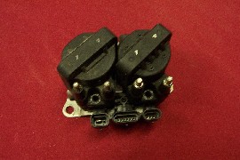 |
| GM DIS control unit with mounting bracket and two coils showing the bottom and top views. | The GM DIS unit assembled . The unit has
two coils; one tagged 1 & 4, and the other tagged 2 & 3, however,
every coil I tested, with the 1 & 4 tag, was bad. (The coils above
are both bad, the good ones are on the bike.) |
 |
|
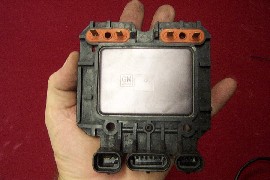
| The GM DIS Control Unit. |
The MegaSquirt II CPU directly supports ignition systems. Their General Motors DIS Ignition Control site is excellent in explaining it's operations. However, I'm using a MegaSquirt I processor. I made this work by installing the MegasquirtNSpark Firmware software and making the MegasquirtNSpark hardware changes to the MegaSquirt V3.0 circuit board.
Making the Reluctor Trigger Wheel and Mounting Shaft
The GM DIS ignition system requires a slotted reluctor wheel. I also needed
a small shaft for mounting the reluctor wheel to the engine crank shaft. I made
both by using a bench grinder, a drill press, and some shop tools.
I also bought a 6" caliper for making some engineering measurements and checking my construction details.
Making these two parts took forever, and a good machine shop can make these parts in less than an hour. However, I had problems finding a shop willing to set-up for a "little" job. So I built them myself. (All my friends are shopless!)
I went to a local welding shop and bought a piece of 6" x 4" x 3/16" steel plate and a 1" diameter steel rod (shaft). I think Home Depot and most local hardware stores stock this material. I cut and grinded the reluctor wheel to a 3-3/16" diameter circle; and I cut the shaft (with a hacksaw) to 3/4" and then grinded it smooth to 0.70" long. The center hole is 6mm. The design is based on the Reluctor Trigger Wheel drawing near the bottom of their web page, However, I changed the wheel dimensions; the wheel diameter required to fit the XJ1100 timing case is 3-3/16".
 |
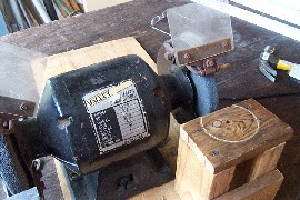 |
| Steve making the reluctor wheel. | Bench Grinder with
a wooden grinding frame. |
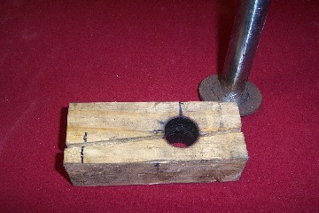 |
| My jig for holding the mounting shaft. I cut a 3/4 " piece of steel from the bar above to make the mounting shaft, and then grinded both ends flat till it measured 0.70" long. It will get hot, real hot...the blackened hole says it all, "Don't touch, you will get burned." Please use gloves and be careful. |
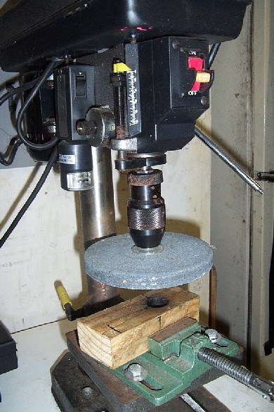 |
| My drill press "tool" for grinding the mounting shaft flat. I placed the mounting shaft near the center of the grinding wheel so it would be stable (less wobble.) Be careful and use standard safety precautions; you can break the grinding stone if you get too physical, and flying stone pieces are never a good thing. |
Assembly (Putting it All Together)
I installed the GM
DIS Ignition system first, got the motorcycle running (using carburetors),
and then installed the EFI system.
I wanted to see if the GM ignition system would work before adding the EFI system.
Assembling the Ignition System
This wasn't hard; but it does require some welding. The GM DIS has three parts:
the reluctor wheel, the VR sensor, and the electronic unit with coil pack.
The Reluctor Wheel and VR sensor replaces the Yamaha timing system. I removed the timing cover from the left side of the motorcycle, unscrewed and removed the timing plate and pickups. I removed the Yamaha ignition system (from under the seat), which was attached to the rear fender, and removed the associated wiring.
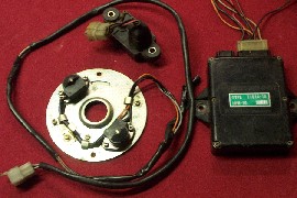 |
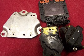
| Yamaha's ignition parts: VR sensor plate, Vacuum transducer, and control module. |
The new reluctor wheel bolted to the same place. However, there was one little
problem, where do I mount the double slotted timing mark in relationship to
top-dead-center (TDC). Where is TDC?
 |
| The reluctor wheel and VR sensor. |
My approach was simple; I removed all the spark plugs, making it easier to turn the engine with an allen wrench. I put a thin screw driver in the number 1 cylinder and as I rotated the engine, my brother felt the piston come to TDC and start down. There's about 15 degrees of rotation where nothing seems to change. By rotating the engine clockwise and then counter clockwise, and holding the screw driver to the top of the rising piston, you can estimate TDC by marking a spot half way between the detected movement. This gets you real close; close enough for now. I took some white paint, applied it to the tip of a flat bladed screw driver and placed a marked on the inside of reluctor wheel mounting shaft, near the frame.
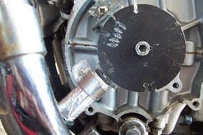 |
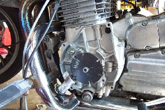
| The reluctor wheel installed with the VR sensor. The far right timing make is TDC. Note: The reluctor wheel turns clockwise, so the timing marks (shown above in white) are After Top Dead Center.(ATDC), my bad! I should have put the timing marks to the right of TDC. As you accelerate, the timing marks advance or fire early, i.e. Before Top Dead Center (BTDC). I'll do better the next time. |
Next, I installed the VR sensor. I took a thin piece of sheet metal and cut it about 1" wide and rolled around the sensor. I placed it close to the old ignition plate screw hole, marked the location, I drilled a hole in the metal holder and used the old ignition plate screw to attached it to the frame. The picture has a good view of my installation. I used a little RTV (silicon) to make the installation "stable" and lock it in place.
Now to set the timing. I used a 1/16" roll pin to lock the reluctor wheel to the mounting shaft. Here's my approach; First, I aligned the mounting shaft to timing mark I made earlier with white paint. Then I loosened the center bolt so the reluctor wheel would turned with effort, but not turn the crank. This was a little tricky because everything wants to turn. I then moved the reluctor wheel so slot 6; the slot just before slot 1 and the timing sync pulse, was just touching the VR sensor. Note: The GM DIS unit "fires" when it detects the slot. Slot 6 should be set just left of the VR sensor. I then took a very small drill bit and drilled a pilot hole through the reluctor wheel and into the mounting shaft. I only drilled the mounting shaft a little so I could get a mark. I removed the reluctor wheel and mounting shaft and used my drill press to drill a 1/16" hole into the mounting shaft to fit the roll pin. I also drilled the the inside of the reluctor wheel, just deep enough for the roll pin to fit, but be captured when I reassembled everything. If you look at the picture above, you can see a small pilot hole near the 3:00 o'clock position, near the center bolt.
One final comment; all this effort gets the timing close enough for starting. Once the motorcycle is running, the Megasqrirt controller electrically sets the timing. I'm off by at least 5 degrees; no big deal. I just re-programmed my timing curves with a 5 degree offset so that everything stayed in sync.
Last step: I made a timing pointer. It's barely visible at the 11:00 o'clock position. I added some timing marks to the reluctor wheel to the left of top-dead center. Don't make this mistake...the timing marks should go to the right of top-dead-center. Boy, what a surprised; I started the motor and my timing light "flashed" to the right on my marks. Oh well, things happen.
The GM DIS Unit
The DIS control unit fits under the tank near the yoke where Yamaha mounted
the original coils. However, I made a few modifications: First, I removed the
integral braking line (more on this later), then I chiseled off the front and
back, coil mounting brackets. The control unit fits snugly, with the coils turned
to the right side of the frame and the electrical plugs to the left side of
the frame. I made two brackets out of 1" steel flat bar. I took the bar,
drilled and tapped the mounting holes using the control unit as a template,
and then dry-fitted the unit in place. Be sure to insert and remove the
DIS connectors before welding the bracket; I got mine to close to the frame
(the first time) and had the cut it off an start over. When I was satisfied
with the dry-fit location, I marked the bend locations, removed the control
unit, and bent and cut the brackets to fit. (cut to fit, paint to match.). A
little welding, grinding, and paint.
 |
| Welding the front DIS bracket to the frame. The rear bracket is also visible. |
Now add the wiring. The GM DIS control unit has three connectors; one for power, another for the VR sensor, and the last goes to the MegaSquirt controller. Get this, You DON'T need the MegaSquirt controller to run the engine; the DIS unit will operate in a "limp" mode and not advance the timing. .
I ran the power for the GM DIS unit from the master relay. And the ground came from the DB37 connector on the MegaSquirt controller.
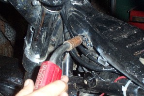
The VR sensor wiring is a two conductor 20 awg shielded cable. I ran the sensor wiring down the lower part of the left frame, came up the frame just in front of the battery, and then forward on the right side of frame to the steering yoke. I soldered the sensor wiring to a GM DIS connector and used heat shrink tubing to seal the splice. I then plugged the sensor into the DIS control unit.
The wiring to the MegaSquirt cpu is a four conductor 20 awg cable. I ran this wiring down the right side on the frame with the VR sensor wiring and attached this cable to the External Wiring Harness.
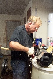
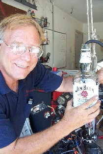
Before connecting a fuel source, I used starting fluid. I bought this from an auto parts store and it comes in a spray can . I took several towels, wet them, and made sure my fire extinguisher was handy. I turned on the key, hit the starter, and it fired. Wow. Note: I did get several backfires, and a flash fire. Be careful, do NOT put your face near the carbs, It burned the hair off my right arm.
I made a temporary fuel tank out of a Jim Beam bottle ... and restarted the
engine.
Here's Steve holding the temporary fuel tank!!!!!
 |
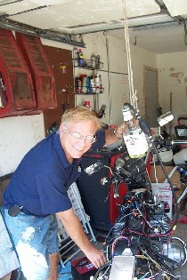 |
| Hey, it's legal, my XJ1100 was born in '82, so it's over the 21 year old drinking restriction. Please notice the outboard motor bulb in the right picture near Steve's left hand, I used this bulb to start the fuel flow. | |
When I was sure everything was working, I took a hacksaw and cut the front of the timing case cover to fit over the VR sensor. As they say in construction, "cut to fit". I used RTV to seal the hole in the case and the VR sensor.
Now that I had the GM DIS ignition system working, I was ready to install the MegaSquirt controller and the EFI System.
Assembling the EFI System
Installing the CPU, Fuel Pump,
Throttle Body & Cable, Temperature Sensors
& Narrow Band O2 Sensor
The first thing I did was removed the carburetors and air box; I threw these
in a recycle box. Then I removed the enrichment cable, also called a choke cable.
CPU
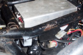
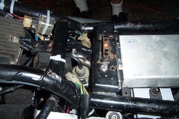
I mounted the CPU directly under the seat just above the battery. I use a chisel
and a cut off wheel to remove a few brackets attached to the seat support frame.
I took a 1" flat steel bar, bent the ends approx. 90 degrees, and made
a CPU mounting bracket. Steve tack welded it to the frame.
 |
(Front of bike) |
|
MegaSquirt CPU and Mounting bracket |
Fuel Pump
I bought a '99 Suzuki Hayabusa in-line fuel pump on eBay
for $81, plus $12 shipping. Don't get confused, the later model Suzuki's have
internally mounted pumps in the tank.
The Hayabusa fuel pump fit nicely on the rear tank frame bracket. I took a piece of 1" x 3/16" flat aluminum bar stock and bent it into a bracket to hold the pump. Then I drilled two small holes in rear tank bracket and used some small metric bolts to mount the pump. Shown below in the middle of the picture are two shinny bolt heads. Note, I locate the pump bracket as far forward as possible on the tank bracket to keep it from interfering with the seat tab.
 |
 |
| The Hayabusa fuel pump fits
nicely under the rear tank bracket. Unfortunately, all you can see is
the fuel pressure regulator, with a vacuum hose attached, in the middle
of the picture, near the electrical connector. |
The fuel pump (under the rear tank bracket)
& CPU |
I used some heavy duty, fuel pump rated, rubber hose for the fuel lines. And I installed a fuel pressure gauge in the high pressure line, just in-front of the fuel rail. (Stan, insert a picture.) The fuel pump produces approx. 38 lbs.of regulated pressure. The high pressure fuel line is less than a foot in length, so it looks good. However, I might come back later and install a steel line, or a braded fuel line. Maybe it's over-engineering, but a broken fuel line could be serious.
The XS/XJ1100's has two petcocks, mounted on the left and right side of the gas tank. I used the right petcock to feed the fuel pump, and the left petcock as the fuel pump return. I installed a metal can type fuel filter in the feed line, cause we all know how gas tanks rust and pickup "garbage". I removed the fuel line octopus system and set the petcocks to "PRI", for Prime. Using this setting allows the fuel to flow straight through each petcock. Note: The petcocks have two connections per petcock, I plugged the connection, closest to the front of the bike, with a plug made from polyurethane fuel line and a metal bolt. I cut off the threads of the bolt and pushed the bolt into the fuel line. I then pushed the fuel line plug onto the connection. Note: The polyutherthane fuel line doesn't need a hose clamp; it fits tight.
At the top of the fuel pump is a regulator, which is visible in the picture. I ran a vacuum line from the throttle body to the regulator. At the bottom of the fuel pump, coming out the side are two fuel line connections. The one nearest the bottom is the pump suction (or inlet) tube. The one slightly higher is the return. This took me a while to figure this out.
Here's a mechanical drawing of the Hayabusa fuel pump. There are two fuel line connections, side by side, coming out the side. The one nearest the bottom, the one that has the 1 (material number) pointing at it is the fuel inlet.
Wiring the pump was easy, I followed the wiring diagram in the MegaSquirt V3.0 Assembly Manual.I mounted the fuel pump relay on the left side of the pump bracket I built and used in-line fuses to protect the circuit. If I do it again, I would buy a fuse bloc; all those in-line fuses are "tacky looking".
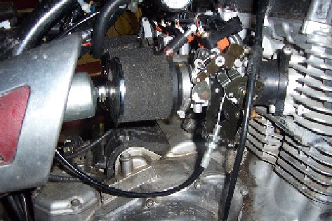
Throttle Body
The Suzuki GSXR 600 Throttle Body (TB) is basically a one for one replacement
for the Mikuni carbs; they just slip into the intake manifold boots.. I used
a complete 2004 Suzuki GSXR-600 throttle body; which includes the Bosche injectors,
fuel rail, and throttle position sensor. I spent $62 on this eBay item. It did
NOT come with a cable harness. which was a mistake on my part. I could NOT find
a harness for a reasonable price, so I made one using some 18 AWG wire, some
small electrical clips, and heat shrink tubing. I did find a 2003 wiring harness
on eBay auction, but alias, the 2003 throttle bodies are very different from
the 2004 and later models; the fuel injector connectors are different and the
throttle sprocket is on opposite side of the motorcycle.
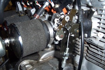 |
| The GSXR 2004 throttle cable attachment lever and UNI (foam) air filters. |
Installing the throttle body was easy, I used a little teflon spray oil, "slimmed-up" the manifold boots, and made a firm push; the TB's slipped right in.
I had to replace the throttle cable; because the attachment hardware was different and the cable was way to short. I was able to keep the original throttle grip, but had a tough time finding the new throttle cable. I finally found a motorcycle shop in Texas City (about 25 miles away) that had the parts. I purchased the cable with a black cable sheath, two barrel ends and attachment hardware for about $30. In searching the web, I found a web site called the Flanders Company where you can order the parts.
 |
| The throttle cable and attachment hardware. |
The throttle body has two butterfly valves; the one nearest the injectors (front
of the bike) is the throttle plates, and I didn't use the butterfly towards
the back of the bike. I took some thin wire, drilled a small hole in the rear
butterfly cam, and tied it open. Some people remove the rear butterfly plates
and then seal the shaft holes with JB Weld; but I decided to leave them on.
One final comment, After I got the engine running, the idle speed was very high; over 2500 rpms. I loosened a throttle plate adjustment locknut (near the throttle plate cam) and slightly adjusted the plates. It only takes a small adjustment, so go slow.
Temperature Sensors
I mounted two temperature sensors; one for the "coolant" (CLT) and
one for the air temp. Mounting was easy, especially since the XJ1100 is an air
cooled engine and doesn't have a coolant loop. I wedged the CLT sensor between
two fins near the middle on the engine just below the throttle bodies. I haven't
secured this sensor yet, but I think a little Permatex high temp RTV silicon
should work nicely. MegaSquirt uses the CLT sensor for warm up settings.
I mounted the air temp sensor on the right side of the bike just behind the side panel using an existing brake line bracket.
The XJ1000 originally had integral braking; where the foot peddle controlled both the rear brake and front left caliper. I hated this design, so I replaced the old braking system with stainless steel brake lines, and re-routed the lines. The hand brake now operates both the front calipers and the foot peddle operates the rear brake. I inserted the air temp sensor into a rubber-grommet bracket originally used for the forward running integral brake line. Note: I love the new braking system, this baby can stop.
Narrow Band O2 Sensor
I mounted a narrow O2 sensor in the right exhaust pipe.
My bike has dual exhaust; cylinders 1&2 combine go down the left side and
cylinders 3&4 go down the right . On the right side where the pipes combine
and just before the muffler, I had the local muffler shop weld on an O2 bung.
They did a great job; but I'm unhappy with the mounting angle. I wish I had
taken extra care in marking the location and slope; the sensor is a little to
vertical. If I hit a deep hole or jump a curve, I could damage the sensor. Oh
well, Life's never perfect, I'll live with the imperfections. It works just
fine. The next time, I'll take some clay, stick it to the pipe and insert a
wooden stick to mark the angle.
Tuning the EFI System
I found this on the MegaSquirt User Forum in October 2006, "So, basically,
get your AFR consistent, adjust the AFR on the dyno up or down for maximum power,
then adjust timing. You may find that you will loose power at some RPM points
and gain at others, but a little analysis will help you optimize the advance
at all RPM points." This made a lot of sense; I decided to follow
his advice.
I need to define some terms (before we get started):
| Configuration | The starting baseline; Selecting the initial values based on sound engineering assumptions (okay, a SWAG, a scientific wild A** guess.) |
| Tuning | Adjusting the configuration baseline; generally done with the engine running and in real-time. |
Let's get started...here's a set of my MegaTune Displays; they're handy for setting up your initial values and for reference. First we need to configure the basic settings: the Engine Constants Table, the EGO Control, Fuel VE Table, Accel Decel Mode, RPM Based Accel, and the Code Based & Output Functions.
The Engine Constants 1 table is dependent on several factors; your fuel pressure and the fuel injector ratings are the most important. I used a '99 Hayabusa in-line fuel pump creating 38 lbs. of fuel pressure and fuel injectors from a 2004 GSXR600 Suzuki. I adjusted the Required Fuel value and found that an injector pulse width of 1.6 ms at idle was about right. I set the Injector Staging to "Simultaneous".
Configuring the fuel Volumetric Efficiency (VE) Fuel VE Table was a little harder. I guessed at the Y-coordinates values (the MAP axis) and selected 20, 30, 35, 45, 50, 60, 65, 70, 80, 85, 95, 100. I set the X-coordinates values (the RPM axis) to 1000, 1400, 1800, 2600, 3400, 4200, 5000, 5800, 6600, 7400, 8200, 9000. This table is a great start, assuming your Engine Constants 1 table closely matches my setting.
Configuring the Spark Table was easy; I took the Yamaha timing charts and typed them into the table. The final tuning requires a Dynometer; so for now, I’m running with my original configuration values. If you compare my ignition table with the Yamaha timing chart, you'll see a little differences; I made a few tweaks as I gained experience riding and listening to the engine.
Crank Setting and Warmup Enrichment
Tuning the Engine:
I knew NOTHING about tuning an EFI engines. I know more now and continue to
learn more as I ride and study my data logs. Reading date logs are important,
so follow these steps:
later, I installed the MegaTune software to my laptop, as well as some MegaLogViewer
software
 |
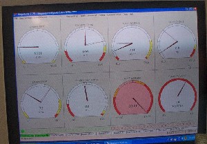 |
| It's running ...Walter and Steve looking at the Megatune display. | |
Final Report
After all this work (and money), how's it running? I'm glad you
asked...the Bottom
Line .
Stan's Biography
I was born Stan Hutchison on June 30, 1954; I attended High School
in San Antonio, TX and graduated from Texas A&M University '76 with a BS
in Electrical Engineering. I married Deborah in '73 and we have two kids, Scott
and Robyn, and one grandchild, Katherine. I work for NASA in the Mission Control
Center at Johnson Space Center, Houston, TX.
Send me a note
if you have questions or need help.
 |
 |
|
|
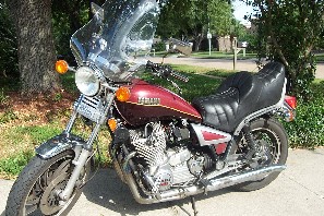
Fishing, more
fishing (offshore), and motorcycles. Stan's other ride, yea, it's old,
but hey, it's a HONDA.
|
||
Acknowledgements (The Good Guys):
Links to some of my favorite Web Sites